This is the second post in a series about plumbing my toilet to flush with harvested rainwater (here's the first). This one is about how we design our system to ensure a reliable supply of water to our toilet cistern, to minimise the likelihood of failure, and to facilitate use. Read on to find out how...
Last time, in the post introducing my desire to be able to flush my toilet with harvested rainwater, I pinned down some objectives for my system, and boldly claimed that an "indirect system" was the best way to achieve them. Let's design out what such a system would actually look like in practical terms.
Specifications
I would like my system to:
- refill the cistern with rainwater when available;
- when no rainwater is available, refill with potable water;
- allow the toilet to be flushed even when there's a power cut;
- fail "safe" so that I don't flood my house or start a fire;
- easily disable the system in the event of a failure; and perhaps most importantly
- prevent backflow of rainwater into the potable water system.
We can achieve almost all of these objectives with a simple header tank.
Header tank
A header tank, or loft tank, is a volume of water that sits high up in your house (usually in the loft) so that it can provide a reliable supply of water at a consistent pressure to feed your appliances. The pressure comes from the hydraulic head of the tank - as it's higher than your appliances gravity pulls water down into them.
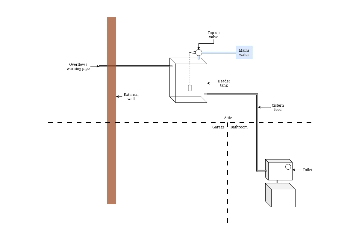
The header tank is supplied by the mains via a top-up valve, which opens when the water-level in the tank drops, and closes again once the water has filled back up to a set level. This refilling happens even in the event of a power-cut, as mains water is supplied under enough pressure to get it up to my loft.
Top-up valves are usually simple ball valves, but as discussed last time we need an air-gap to prevent backflow from contaminating the potable supply, so we require something like a RainAid instead.
A warning pipe acts as an overflow, so if our valve fails we won't flood our house - the excess will be routed outside where we'll see it coming out of the pipe and go and fix it.
This simple system checks off nearly all of our objectives:
- refill the cistern with rainwater when available; ❌
- when no rainwater is available, refill with potable water; ✅
- allow the toilet to be flushed even when there's a power cut; ✅
- fail "safe" so that I don't flood my house or start a fire; ✅
- easily disable the system in the event of a failure; and perhaps most importantly ✅
- prevent backflow of rainwater into the potable water system. ✅
The only thing missing is using rainwater to fill the loft tank when it's available.
"Dumb" rainwater harvesting
To fill our header tank with harvested rainwater we can pump it up there. Needless to say, the person wiring your pump will need to be a "competent person".
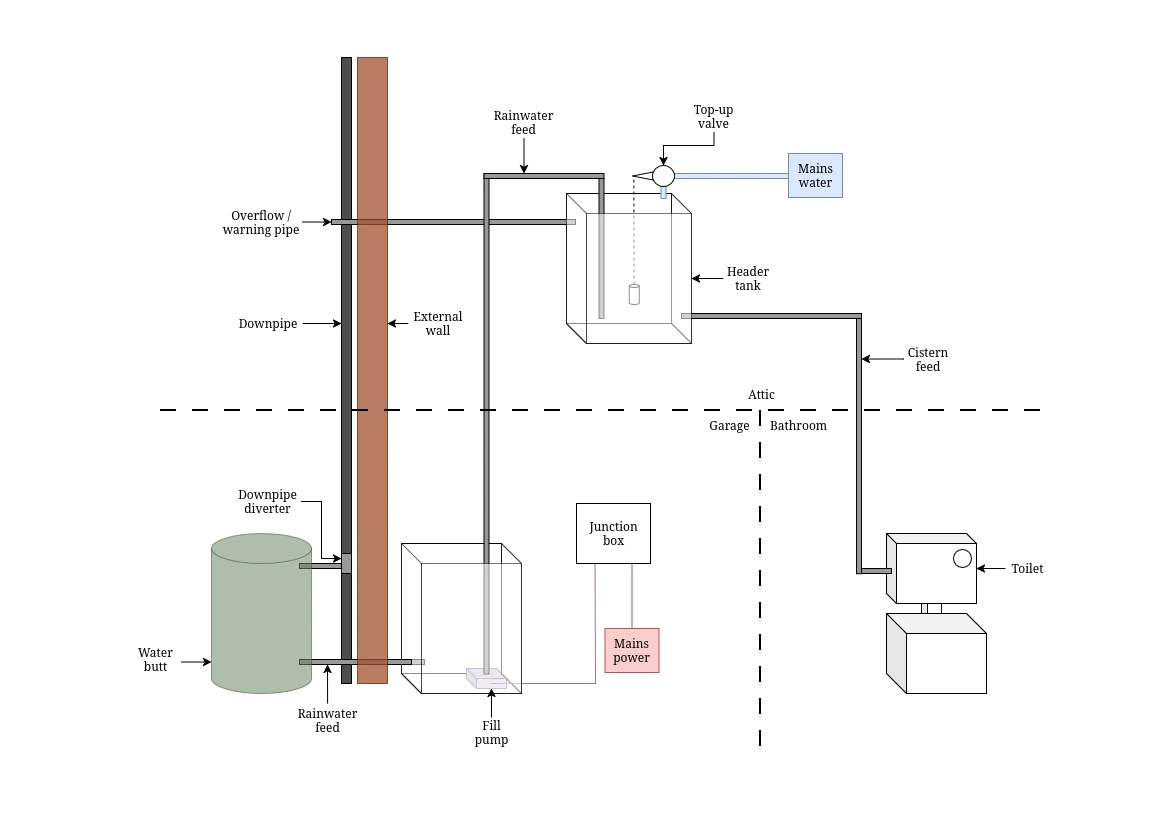
We've added a water-butt to our downpipe, and a feed connecting this to a tank in our garage from which we use an electric pump to move water up into the loft tank. Strictly speaking this second tank isn't necessary, but it means that we can keep all of our electronics inside our garage and only need one hole in our garage wall for a single rainwater feed. We can stick a ball valve on this feed if we want to in order to easily isolate it from our rainwater feed for maintenance and cleaning.
This improves our ❌ to a 🟠 in terms of "refill the cistern with rainwater when available", but we'd have to do this manually, and the obvious challenge with this system is knowing when to turn on our pump. We can't run it 24/7 as it would both overfill the loft tank, wasting that harvested rainwater by spilling it out of the warning pipe, and run the pump dry. And we can't just turn it on manually when we need it because we don't know when we need it, because we've no way of knowing how much water is in our loft tank without climbing into our attic and peering in.
Thankfully, there's an easy fix for this.
Float switches
With the addition of two float switches we can augment our "dumb" system so that it activates our pump to move rainwater up to our loft tank only when there's space for it up there, and only when rainwater is available.
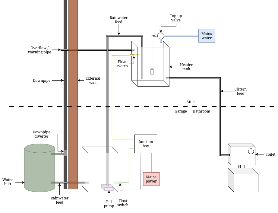
Float switches are simply switches that change state when the water-level in a contain moves past a set point. They're often reversible - install them one way up and they're "normally open" with the circuit broken when the water level is below them and connected when the water level rises above them, but install them the other way up and they're "normally closed" with the circuit connected when the water level is below them and broken when it rises above them.
- We install one "normally open" in the base of the rainwater tank in the garage, just above our pump. This will be closed when there's enough rainwater in there to feed the pump, but once it drops below this set-point the float switch will open and break the pump circuit.
- We install one "normally closed" in the top of our header tank in the loft, just below the warning pipe. This will be open as long as the water level in the tank is above the switch, but as soon as the toilet is flushed and the water level drops it'll close the circuit, effectively demanding more water from the pump.
Whilst can get float switches rated for mains loads that you could wire directly in-line with your pump power feed, interfacing mains systems with water is generally considered a "bad idea". A "better idea" would be to have the float switches on a low-voltage circuit that connects to a relay that can switch the mains power for the pump. DIN enclosures and DIN rail mounted relays are cheap, as are low voltage power supplies, so I'd suggest that your "competent person" installs those instead.
Monitoring performance
This is all we really need - we get to ✅ our "refill the cistern with rainwater when available" and complete the set of green ticks - but there's one more improvement that we can make.
At the moment it's a very low-fuss system, it just gets on with it, but we don't have any visibility into how well it's performing. We don't know how much water is in our header tank, whether we're flushing with rainwater or potable, how much potable water we've saved etc. The easiest way that we can gain this insight is to simply start measuring the water-level in our header tank, and create an interface that allows us to explore the data.
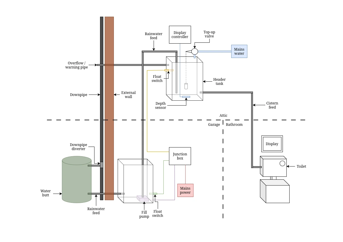
With sufficient temporal resolution, the water level in the header tank is all we need to derive quite a lot about how our system is operating.
- If the water level drops then we've used some water. We can derive how much we've used from the tank geometry, and use this to count flushes.
- If the water level is above the mains backup set-point then we can attribute any rises to the rainwater pump, and keep track of that to calculate potable water saved.
- If the water level is below the mains backup set-point then we can attribute any rises to the mains backup, and keep track of that to calculate potable water used. (There may be an edge case where some of this is rainwater backup, but it would be extremely rare, so for this sort of system we don't need to worry about it).
We might also want to think about the electricity used by the pump in our system, and we could use power monitoring smart plugs or similar to calculate this if we wanted to.
And in terms of choosing an interface, the world is our oyster - we could use a web-page, an app, or something cooler (watch this space!).
What's next?
So we've decided how our system will work, and assessed what regulatory hurdles we may have to jump over, so the next step is to work out what materials we'll actually need, then get started! Keep your eyes peeled for the next post, where I'll go through a BOM, work out how much it will cost, and get ready to install.