This is the second post about a project to build a cave surveying device. You might want to read the first post before embarking on this one.
So far we've worked out how to read the distance measurements that the device writes on the serial pins of its MCU, but we've been doing this by hand on a computer. In this post we'll look at how we can use a microcontroller to read those distance measurements, along with measurements of heading and inclination from an accelerometer and magnetometer, and send them over serial to other devices.
The Microcontroller
There are a whole range of microcontrollers suitable for this sort of task, but I'm working with the Adafruit Feather nRF52840 Express. I chose this board to facilitate the use of Bluetooth LE, but many other boards are suitable. If you use an arduino-compatible board then you may even be able to copy and paste the code that we write for it with very few changes.
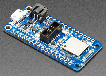
There are a few features of the Feather nRF52840 Express in particular that are desirable for this project:
- Hardware UART pins enable us to read serial data from the LDM whilst still being able to write to the USB serial for debugging
- The built-in nRF52840 radio is Bluetooth LE compatible, and libraries already exist to facilitate comms
- Built-in voltage regulators and connectors facilitate the use and charging of LiPo batteries
- An addressable multicolour NeoPixel LED and 'USER' switch extend control and feedback options
The acceler/magnet-ometer
In order to determine the inclination and compass heading of the unit we need a magentometer and 3-axis accelerometer. To simplify the wiring I have chosen to use a board that contains both; Adafruit's LSM303DLHC.
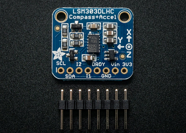
This communicates using I2C, and Adafruit has already developed libraries that make it easily addressable.
Connecting the LDM
With built-in hardware UART pins it's very easy to hook up the LDM to the serial port; connect:
- TxD contact on the LDM to the RX pin on the Feather
- RxD contact on the LDM to the TX pin on the Feather
- -ve battery terminal on the LDM to the Feather's gnd pin to give a reliable reference voltage.
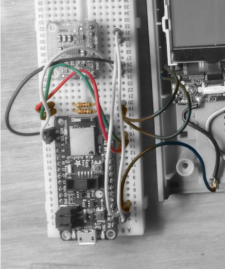
There aren't built-in pull-up resistors on the Feather's TX/RX pins but since we're not expecting the signal to be floating at any point then this isn't an issue. I have put a couple of resistors on those pins to protect them from me being an idiot whilst I was first experimenting with the circuit, but I don't think that they're strictly necessary.
Connecting the LSM303DLHC
It's very easy to wire up the LSM303DLHC module to the Feather as it communicates over I2C and the Feather has available SCL/SDA pins. As such you just need to connect:
- SCL on the LSM303 to SCL on the Feather
- SDA on the LSM303 to SDA on the Feather
- gnd on the LSM303 to gnd on the Feather
- 3.3v on the LSM303 to 3.3v on the Feather
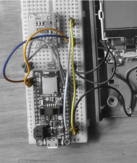
All the necessary pull-up resistors are already in place on the Adafruit breakout board so there's no extra components required in this case.
Powering the LDM
At the moment we have two distinct components that we're combining - the LDM which uses 2x AAA batteries in series (for 3V), and the Feather which can be powered over USB or using Li-ion batteries. We don't want to have to use two separate power supplies, so instead we're going to see how we can power the LDM from the Feather.
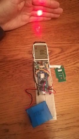
Using an ammeter we measure that, with the laser on and a measurement being taken, the LDM never draws more than 135mA of current. It's not clear from the documentation what maximum continuous current the nRF52840 Express's 3v output pin is rated for, but based on other similar Feather's it's likely to be at least 250mA. The LSM303DLHC datasheet claims a 1mA peak current draw, so the 3v pin can easily power both components. We now only need to power the Feather itself, which should be easy as it has an onboard JST PH connector for external battery packs.
I'm lucky enough to have one kicking around after salvaging parts from an old Bluetooth speaker, allowing me to quickly prototype a portable version (right) with the LSM303DLHC tucked out of the way beneath the LDM board.
What's next?
So far we've worked out how we can decode readings from the LDM, and how we can wire it up to a microcontroller to allow us to work with those measurements. We've also wired up a magnetometer/accelerometer so that we can take compass headings and inclination measurements. Finally we've added a battery pack to keep us portable.
The next step is to develop some software that can take readings from the LDM, magnetometer, and accelerometer and convert them to distance, heading, and inclination respectively. This will likely require some geometry and calibration of the sensors. That will be the topic of the next post.