In the Venn-diagram of my main hobbies there's a significant subset of Caving and Amateur electronics; in fact the British Cave Research Association has an entire journal, the Cave Radio & Electronics Group, dedicated to the subject. This project falls perfectly into that subset.
I'm reverse engineering a SNDWAY Laser Distance Meter (LDM) so that I can add magnetometer, accelerometer, and Bluetooth modules in order to make a DIY DistoX2 paperless cave surveying tool. This will never compete with the accuracy, robustness, or usability of a DistoX2, but it's not supposed to compete, it's just a bit of fun for me. It's also a lot cheaper than me buying a proper one. This also isn't the first attempt at reverse engineering a laser rangefinder, but as these devices differ greatly I still think that it is worth documenting my progress with this one.
The LDM
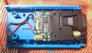
I wanted a reasonably cheap LDM with a long range for this project, so I went for the D1 SW-T100 100m LDM from SNDWAY. These knock-off LDMs go for about £25 on eBay, but are poorly labelled and shipped from China so you rarely know exactly what you're going to get until you actually get it. Even the case on them doesn't always correspond with what's inside them. This is what I actually received:


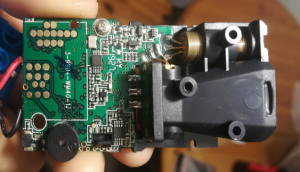
This is the main board. It is accessed by removing the front case, unclipping the ribbon cables between the LCD and button boards and removing them, then unscrewing the board from the back case. Things of note are:
- ARM STM32F030C8T6 Microcontroller
- LQFP48 48-pin package
- RxD/TxD pins broken out to contacts on the board
- Piezo-speaker
- This will be significantly magnetic so will need to be removed before I add the magnetometer
Establishing Serial Communications
So having found RxD/TxD contacts on the board, and confirmed that they match up with appropriate pins on the MCU, I soldered some jumpers to them and hooked them up to a breadboard. I then sampled them using an oscilloscope as I powered on the device:

As the device powers on it starts pulling a nice clear signal on the TxD pin. A quick measure of the duration of a single bit using the scope gives us the baud rate; 115.2kbaud. Hooking it up to serial monitor such as PuTTY facilitates decoding the signal. There's a great tutorial on how to use an Arduino as a USB Serial Bridge if you don't have a dedicated one. The decoding itself is thankfully easy as the signal is just ASCII with NL&CR line-endings in 8N1. So when we power up the device we receive 3 lines:
SPP:setName = SNDWAY LDM STUDIOSPP:setBR 9600SPP:saveConfigure
Some initial observations:
- The communications are following the Serial Port Profile. This profile describes how bluetooth devices can emulate serial cable connections over RFCOMM.
- The initial configuration sets a new baud rate of 9600 baud for future communications.
So we reconfigure PuTTY to read at 9600 baud rather than 115.2kbaud and turn the device on again. This time we get two lines:
SPP:setName = SNDWAY LDM STUDIOSPP:saveConfigure
Reading Distance Measurements
Now, whilst listening at 9600 baud, we take a distance measurement. The measurement is displayed on the LDM's LCD screen and we get something that looks like this in ASCII on the serial:
ATD..Ad........~#
This doesn't look like it's supposed to be ASCII encoded so we'll represent it in hexidecimal from here on in i.e.
41 54 44 00 00 41 64 00 00 00 00 00 00 00 00 7E 23
These are always 17 characters long. All measurements are prefixed by 41 54 44 (ASCII ATD) and suffixed by 23 (ASCII #), enabling us to easily determine measurements whilst parsing from the serial buffer. The penultimate value 7E varies seemingly at random, so I will assume that it's some form of checksum that we can ignore for the moment.
The interesting bit is therefore the remaining 12 characters:
00 00 41 64 00 00 00 00 00 00 00 00
This is our distance measurement, zero padded, so we just need to strip the padding and convert it to decimal i.e.:
0x4164 = 16740
In this case the LDM's LCD reported a distance of 1.67m, so our units are \(m\times10^{-4}\).
What's next?
So far we've just been reverse engineering this Laser Distance Meter so that we can work out how to read the measurements it takes over a serial connection. But we haven't covered how we'll process these measurements, send them out over Bluetooth, and combine them with compass bearings and inclinometer readings.
This is where a microcontroller comes in, which can do all that processing with a very low footprint and power consumption. I'll introduce the microcontroller that we'll use in the next post, where we'll also look at programming it, and getting it talking to our other components.